VMU Hacking
by: dosman
11-2003
A few
years back when the Sony Dreamcast was still new and cool, people started
playing with a device called the Visual Memory Unit (VMU). This is a memory card
for the Dreamcast, but with a twist. It has a small LCD screen and basic NES
style controls. It connects into your controller and gives you additional
animations for the game you are playing as well as being able to store game
saves. It can also be used to play games by itself. An interesting concept to
say the least... So anyway people started figuring out how to directly connect
to the devices and do their own custom coding for them.
Now let me make a statement here for the
elitists reading this: I have done nothing all that original here, I have only
followed directions of others to make this. The VMU hacking scene peaked back
around 2000 so I am late to the party. Really all I am doing here is making an
adapter cradle for my VMU, but with a bit more style than most ;). And with that
warning out of the way, here we go.
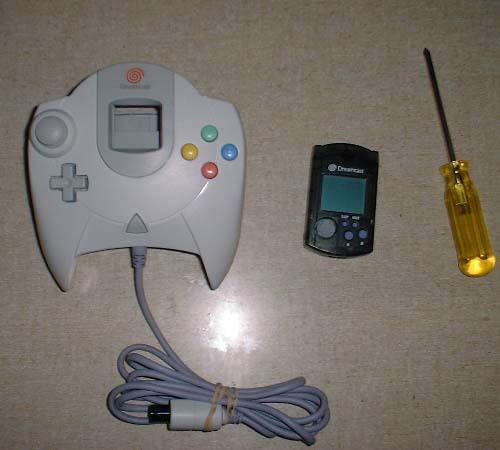
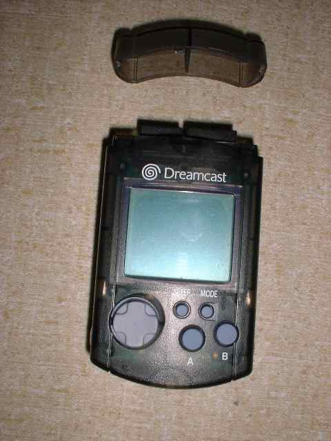
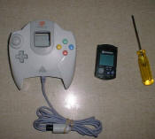
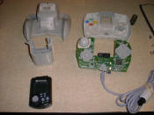
Here are my sacrificial devices, a nice
translucent charcoal VMU for $3 and a Dreamcast controller for $5 from the used
game store at the mall. I got the controller so I could make a nice adapter
without soldering wires directly to the VMU.

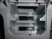
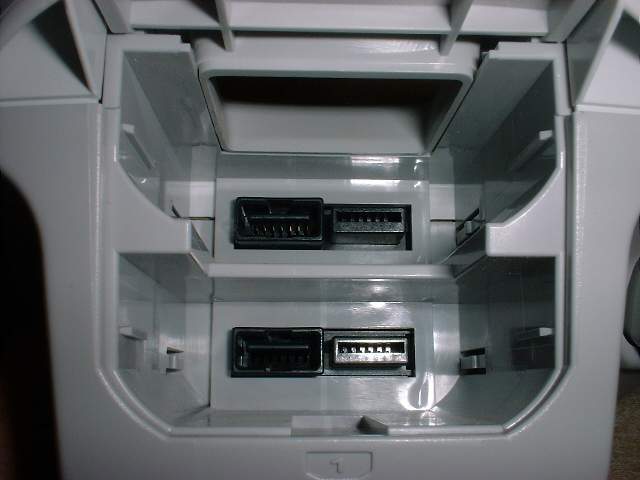
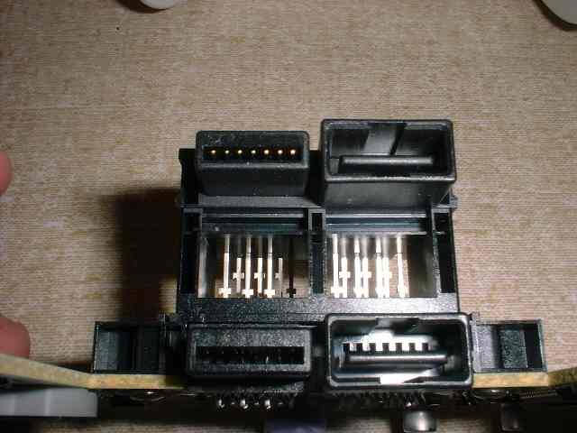
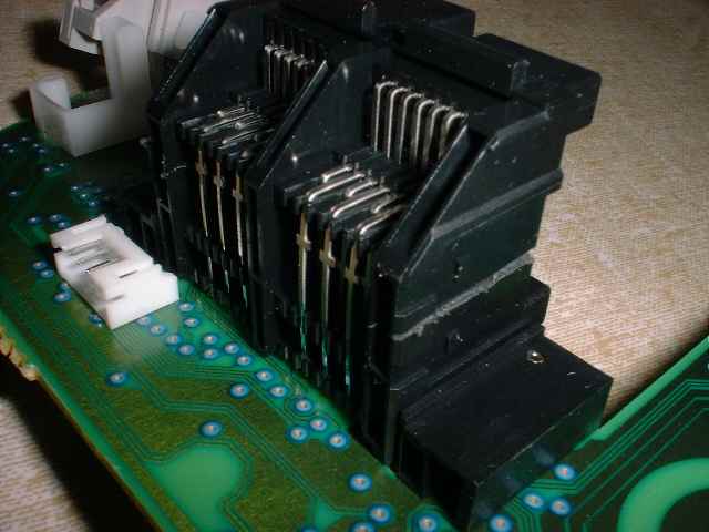
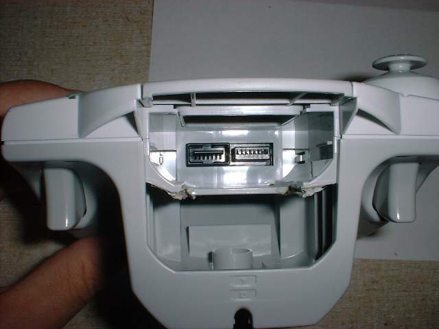
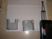
Staring down the VMU sockets and a disassembled controller


I used a box cutter to slice the plastic and side cuts to do
the connector pins

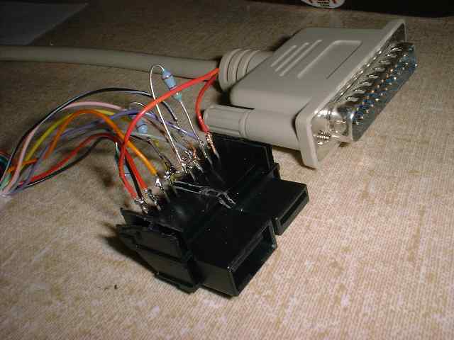
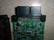
The connector freed and wires soldered to the socket. Note:
this shot was before I added the 4.7k Ohm resistors
Here is the pinout for the adapter. This
nicely formatted layout is stolen directly from John Maushammer's terrific VMU
site.
LPT Pin In/Out LPT Signal Name     VMU Pin  VMU Name             #define
------- ------ ---------------     -------  -------------------- -----------
   2     I/O   Data Bit 0             12     PC2VMU clock        OUT_CLK
   3     I/O   Data Bit 1             10     PC2VMU data         OUT_DATA
   4     I/O   Data Bit 2              4     PC2VMU delayed data OUT_DLYDATA
   5     I/O   Data Bit 3              6     PC2VMU handshake    OUT_HSK
  10      I     -ACK           **      3     VMU2PC clock        IN_CLK
  11      I     BUSY           **      5     VMU2PC data         IN_DATA
  13      I     SLCT           **     11     VMU2PC delayed data IN_DLYDATA
18-25    ---    Ground               7,8     Ground
                           1-14 Make sure these are connected to each other
                                 so that the VMU's drivers are enabled.
*** Also connect these pins through 4.7kohm resistors to ground. You need a total of 3 resistors.
(note: depending on your parallel port, a different value may be needed. If you want to
live dangerously, you can omit them (but I didn't and wouldn't recommend it))
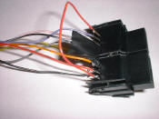
I used a standard DB25 printer cable and
cut off the Centronics printer connector for my cable. Then I used an Ohm meter
to make a map of which wires where connected to which pins. I think it took
about 35 minutes to get this portion completed.
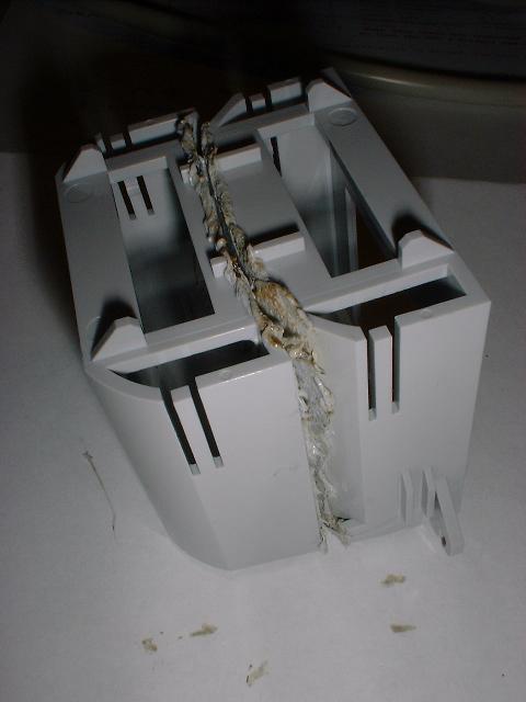
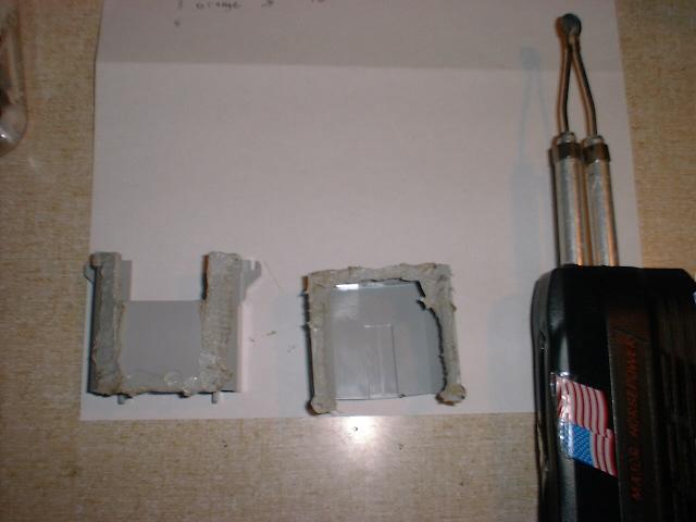
Here the VMU socket housing is being worked
on.
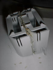
I used a soldering gun with a cutting tip to separate the two
VMU holders
 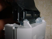
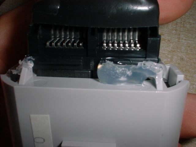
Once again, hot glue is the way to go. With the VMU plugged in
you can CAREFULLY glue the connector in place. You will want to be sure you
don't accidentally glue the VMU's connector to the grey housing, you can see I
didn't just run glue all over the entire connector for this very reason. It is
still sturdy even with this small amount of glue used.

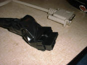
The reassembled Dreamcast controller. The first VMU port is
still functional, this controller will go to my friend that actually owns a
Dreamcast.
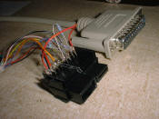 
Note that this is before I glued the connector the grey
housing. Also notice the 4.7k Ohm resistors now in place. As I had read,
connecting the VMU without them does cause the screen to black out. Fortunatly
my unit was not damaged, but it would not accept files like this. The resistors
corrected both problems.
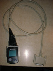
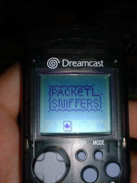
The completed unit! Yea!
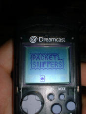
Tada! A little advert for a cable access show a friend and
myself are putting together.
Now that I have this completed
I will start some work on some animations of my own. I may even try my hand at
some assembler code if I feel really motivated. I will post some of my creations
below once I get something worthy of posting.
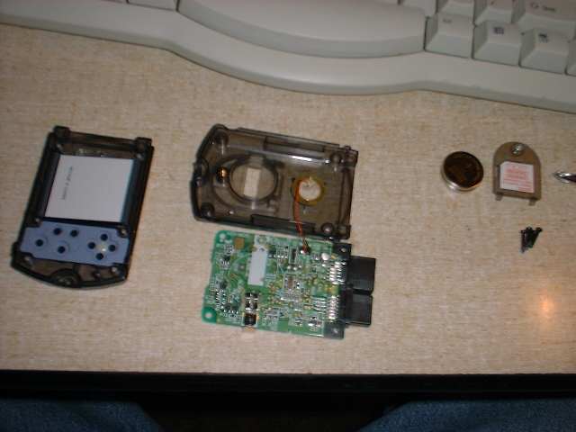
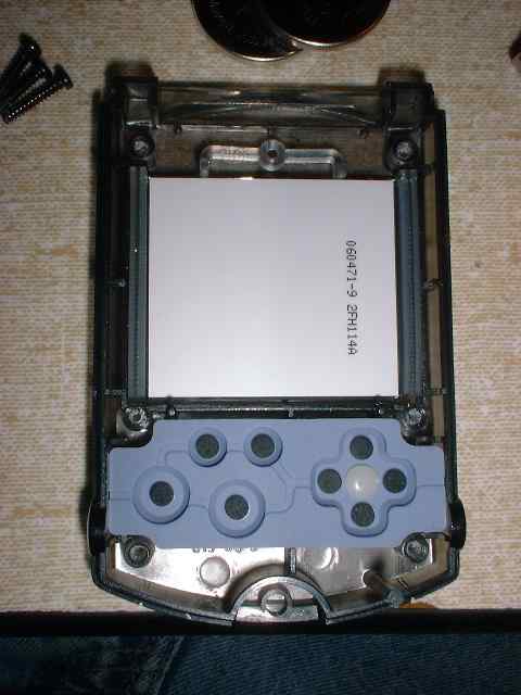
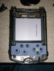
Gutted VMU
I decided to take the VMU apart so I could clean
the screen properly. Here are some pics of that near fiasco.
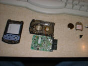
Pretty...
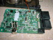
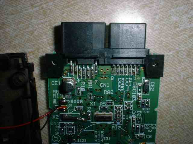
Here you can see the circuitry really well along with the pin
numbering stenciled onto the VMU circuit board.

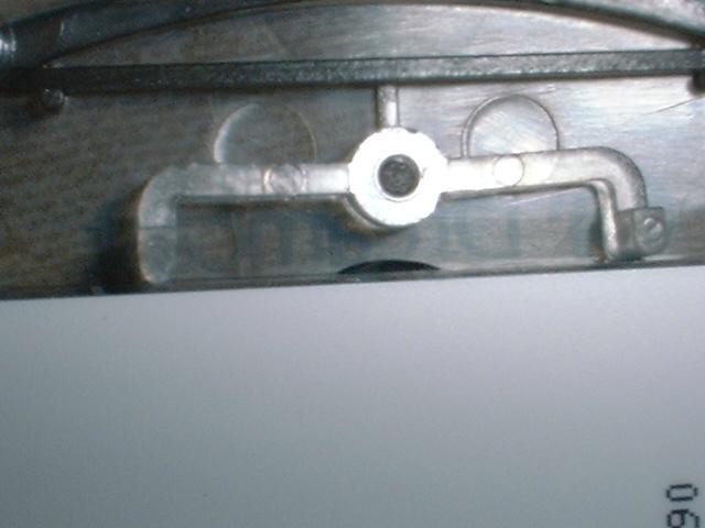
If you take out the LCD screen, watch which way it goes back
in as I did not. There is a small "bump" on the LCD glass that goes to the top
of the VMU, you will notice on the left picture.
Additional Info
This site has a ton of good VMU info and is where I got all of my info and
tools for doing this project:
http://www.maushammer.com/vmu.html
Here is another site that has some good VMU animation creation
tools:
Notice: This site is not in any
way affiliated with Sony or any of it's subsidiaries or affiliates.
|